ENGINEERED FOR SPEED
Design Phase
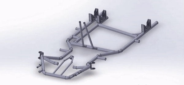
After researching different models, categories, performance characteristics and talking to drivers, a better understanding of what we could incorporate into our design became more clear. The adjustability at points which the chassis interacts with external parts of a complete kart presented itself as a clear way that we could add value to the driver's experience as well as make it easier for an engineer who is tuning the kart. The most important aspects of the chassis we wanted to optimize were the spindle mounts which account for the caster and camber angles, the front anti-roll bar design, rear diagonal bar, and bearing carriers. Each of these can be broken down further in the following section.
Spindle Mounts
Starting at the front of the kart, the spindle mounts were an important component of our design. The spindle mounts are where the caster and camber angles are determined which are two important characteristics when racing. While the following image is for a traditional automobile, it still illustrates what these are and how they differentiate from each other.
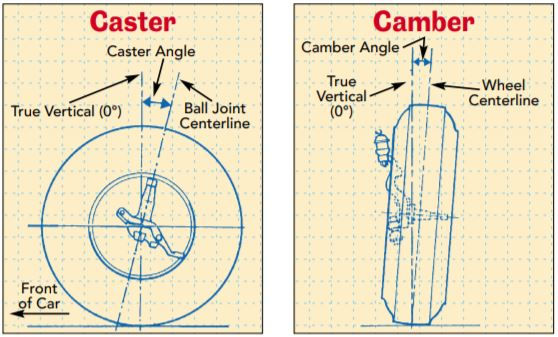
Caster and camber have a direct relationship and are essential for maximizing a tire's contact patch with the ground when cornering, which is essential for maximizing grip. The greater the contact patch, the better grip, the faster you can go around a corner. Being able to have a wider range of adjustments for these characteristics would allow a tuner to adjust for driver style, but more importantly for the technicality of various track layouts.
Front Anti-Roll Bar Design
The next component that was considered for our design was the anti-roll bar design. This is important for the flexibility of the front end of the kart. The way this aspect of a chassis works is there are hollow tubes that are part of the chassis and stick out towards the middle of the kart. Then, an interchangeable anti-roll bar can be inserted into each of the two sides. Different anti-roll bars are made of materials with different properties which focus around their flex characteristics. This allows for varying levels of stiffness in the front end of the kart. There are two orientations that are currently used in industry, in-line and set-back. Below is an example of a set-back orientation.

In-line refers to in-line with the spindle mounts which is where the front axle is attached to the chassis. This orientation allows for the anti-roll bar to have a greater affect on the stiffness of the front end of the kart. Set-back orientation refers to the mounting points being slightly behind the spindle mounts. This orientation serves the same purpose, but the input from the anti-roll bar is diminished. Due to the varying flex characteristics of anti-roll bars, the in-line orientation was chosen as it would allow for the widest range of stiff vs. flexible.
Rear Diagonal Bar
The rear diagonal bar was a focal point of our design. This is the main crossmember in the rear of the kart which has the greatest impact on flexibility of the chassis. While it may seem like one of the most simple aspects of the chassis, it is responsible for achieving some of the most desired responses while cornering. Having a flexible rear end of kart means that when cornering, the inner rear wheel has the ability to lift off the ground maximizing the contact patch of the rest of the tires leading to faster cornering speeds.
Bearing Carriers
The last point of the chassis which was considered for our design was the bearing carriers. These are where the rear axle mounts and have more function that just that. These are where the rake angle of the kart can be adjusted. The rake angle is another important concept to understand and is easiest to conceptualize through a visual.

The rake angle is essential to any high performing racing vehicle as the higher the rake angle, the more downforce there is, sucking the floor of car down to the track. The reason this occurs, is because when air is flowing past, under, around the vehicle and the front is lower than the rear. Since the space between the track and the floor of the vehicle expands as it goes back, it creates a lower pressure underneath the car and a high pressure flowing over the car which is what keeps the car glued to the track. Again, being able to adjust this angle customized to driver style or track conditions is very advantageous. To achieve this, there are different adjustment holes on the bearing carrier which raise, or lower the rear axle. Most chassis only have three of these adjustments, however in our design we have five.
Finding The Sweet Spot
The challenge that was faced when coming up with the final design for our chassis was maximizing adjustability, without compromising performance for each of these components. In order to find the "sweet spot" simulation software like ANSYS was used. After building the models of both competition chassis as well as our first conceptual design, different loads were applied to simulate driving conditions. The characteristic that we were looking for most in our simulations was the flexibility of the rear half of the chassis. Below is one of the simulation results which simulated a left hand turn and how the chassis would react.

After tweaking our model several times and re-running the simulations, we finalized our design and moved onto the fabrication phase.